


The Cleanroom HVAC crisis: Solving Humidity and Operator Overheating
Maintaining strict environmental parameters within a controlled facility is a rigorous engineering challenge. While particle counts often receive the primary focus during design and validation, thermal comfort and moisture control are equally critical to operational integrity. During the humid summer months across the United Kingdom, many facilities managers face a severe operational crisis: their heating, ventilation, and air conditioning (HVAC) systems fail to maintain relative humidity and temperature baselines.
When a cleanroom HVAC system loses control of moisture levels, the consequences extend far beyond simple staff discomfort. In the life science sector sweat is a major contamination risk and in the advanced engineering
sector high humidity levels can un-stabilise process materials risking explosions.
Different types of dehumidification
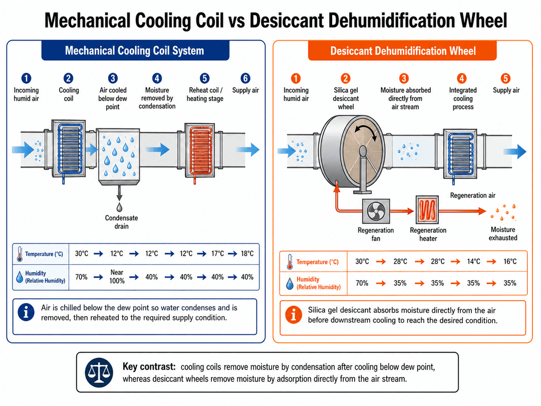
There are two different ways to dehumidify air. The standard system is to use a cooling coil which lowers the air temperature below the dew point to extract the water, the air is then heated before entering the cleanroom. For those requiring low humidity environments it is necessary to use a silicone wheel otherwise know as Desiccant Dehumidification Wheel, which heats the air to evaporate the moisture and the air is then cooled before entering the cleanroom.
Why Does Cleanroom Humidity Control Fail During Humid Months?
A simple reason may well come back to the initial design that may not have accounted for enough moisture load. The reasons for this maybe a miss calculation but quite often it is due to a lack of knowledge at the design stage of the moisture burden of the process undertaken in the room.
Additional load can easily and inadvertently be added over time. More staff, increased production, new process machinery will all increase the moisture load in the cleanroom. Extract (LEV) added to a cleanroom after commissioning will require an equal volume of make up air to compensate for the volume extracted. This air needs to be replaced to maintain pressure cascades by increasing the make up air. This make up air is taken from outside of the cleanroom and may come with its own moisture load. Couple this with an increased humidity level during the summer months and the HVAC system will struggle to maintain its set point.
To understand why a cleanroom system struggles more when external ambient humidity rises, it is necessary to examine how standard air handling systems interact with water vapour. Many facilities rely on systems that perform well in spring and winter but fail under peak summer loads. This failure usually traces back to a fundamental misunderstanding of dew point mechanics.
The Fundamental Challenge of Dew Point Control
Relative humidity is entirely dependent on temperature. A room with 50 percent relative humidity at 20 degrees Celsius contains far less physical water than a room with 50 percent relative humidity at 25 degrees Celsius. Because of this relationship, focusing purely on relative humidity sensors can mislead facilities managers.
Sensible Heat versus Latent Heat Disconnection
An environmental control system must handle two distinct types of thermal energy: sensible heat and latent heat. Sensible heat is the energy that changes the air temperature, which can be read directly on a standard thermometer. Latent heat is the energy bound within airborne water vapour.
When warm, humid fresh air enters a building, it carries a heavy latent heat load. Standard cooling systems are frequently configured to respond primarily to sensible heat changes. When the thermostat detects a temperature rise, the system cools the air but may fail to run long enough or drop low enough in temperature to condense and remove the latent moisture.
The Crucial Role of the Apparatus Dew Point
To remove moisture from the incoming air stream, the air must be cooled below its dew point temperature. This is the temperature at which water vapour condenses into liquid droplets. The surface temperature of the cooling coil within the air handling unit, known as the apparatus dew point, must be kept low enough to squeeze moisture out of the air. If the chilled water loop feeding the coil fluctuates by even two degrees Celsius, the system will fail to hit this dew point, allowing humid air to pass straight into the cleanroom supply ducts.
The Failure of Standard Commercial Air Conditioning Systems
Many modular cleanrooms are retrofitted into existing industrial spaces using standard commercial comfort cooling hardware. While these systems are acceptable for typical office spaces, they are not designed for precision contamination control environments.
Why Under-Sized or Over-Sized Cooling Coils Fail to Dehumidify
A common misconception is that installing a larger cooling coil or a higher capacity condenser will solve summer humidity issues. In reality, an over-sized cooling coil often worsens humidity problems.
When an over-sized system turns on, it lowers the room's sensible temperature very rapidly. Once the target temperature is reached, the compressor shuts off. Because the unit ran for only a brief period, the cooling coil never spent enough time below the dew point to remove significant water vapour. The room becomes cold but remains damp and clammy.
Conversely, an under-sized coil lacks the total thermal capacity to lower the air temperature down to the necessary dew point under peak outdoor summer loads, resulting in simultaneous temperature and humidity spikes.
What Are the Hidden Sources of Heat and Moisture inside a Cleanroom?
When troubleshooting a failing HVAC matrix, engineers often audit the incoming fresh air supply but struggle to pinpoint internal heat generation. Often the equipment list and process destails have not been confirmed at the time of design and so an assumed volume is used in the calculations.
The Thermal Load of HEPA Fan Filter Units (FFUs)
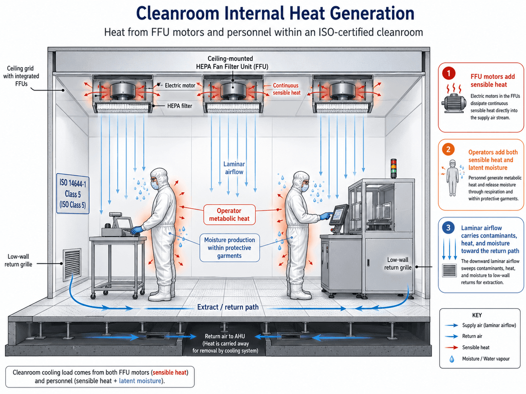
To maintain strict ISO particulate classifications, cleanrooms require high air changes per hour. Some cleanroom designs use ceiling-mounted Fan Filter Units. These units represent a continuous source of internal sensible heat.
Motor Heat Dissipation and Airflow Resistance
Every FFU contains an electric motor and an internal fan impeller. As these motors operate continuously to push air through dense HEPA filters, they convert electrical energy into mechanical movement and waste heat. This thermal energy is dissipated directly into the cleanroom air stream.
In a high-density facility, such as an ISO Class 5 space, the collective heat generated by the FFU motors can raise the air temperature by several degrees before the air even reaches the working floor. If this energy input is not specifically accounted for in the initial HVAC system design, the cooling system will constantly run behind the true thermal load of the facility.
Filter Blinding and Static Pressure Elevation
As HEPA filters collect particulates over their operating lifespan, their structural resistance increases. This increase in static pressure forces the FFU motors to draw more electrical current to maintain the required face velocity. Increased current draw results in higher operating temperatures and elevated heat dissipation into the clean space, causing a progressive thermal load increase over years of operation.
Human Latent Heat Loads and Operator Sweat Risks
For the life science sector the most volatile and dangerous source of moisture within a controlled workspace is the human body. People constantly release moisture through respiration and perspiration, and these rates escalate dramatically if the work environment is uncomfortable.
Biocontamination Vectors from Overheated Personnel
When an operator becomes uncomfortably warm, the body activates its natural cooling mechanism: sweating. Inside a non-porous cleanroom garment, this sweat cannot evaporate efficiently into the surrounding air. The garment becomes damp, creating a capillary action that allows microbes on the skin to migrate outward through the fabric weave.
Once moisture saturates the clothing material, the operator becomes a significant bioburden hazard, shedding viable organisms and skin cells into the ambient environment. This issue directly threatens compliance for medical device manufacturing, packing, and pharmaceutical compounding.
Quantifying Respiratory Moisture Output
Even an operator sitting perfectly still breathes out a measurable volume of water vapour. In a crowded facility where personnel are moving components or performing manual assembly tasks, the collective respiratory moisture output can introduce several litres of water per hour directly into the air. If the air change rate and moisture extraction loops are not perfectly calibrated to match personnel density, relative humidity will drift upward during busy operational shifts.
How Do You Properly Balance Recirculated Air Against Fresh Air Exhaust Requirements?
Resolving a humidity crisis is rarely as simple as turning down the chiller temperature. It requires balancing the volume of air recirculated within the facility against the fresh makeup air drawn from outside, while simultaneously factoring in local exhaust requirements from process machinery.
The Makeup Air Balance Formula
British building regulations require low levels of air change rates to maintain oxygen levels for the occupants and dilute odours. Cleanrooms must draw in external fresh air in far greater volume, often called makeup air, for two reasons: to replace air lost through process exhausts and to maintain a positive pressure gradient that prevents unfiltered outside air from entering through doorways.
Pressurisation Needs versus Outdoor Moisture Infiltration
Every cubic metre of fresh air drawn from the outside during a humid UK summer introduces a substantial moisture load into the air handling system. If a facility opens its exhaust dampers wider than necessary to clear fumes from an extraction process, the HVAC system must pull in an equivalent volume of hot, humid outside air to maintain the building's target pressure. To minimise this moisture introduction, engineers must audit all local tool exhausts and reduce them to the minimum safe flow rate required for worker safety.
Calculating the Optimum Recirculation Ratio
To achieve stable humidity control without massive energy expenditures, systems maximise the volume of air they recirculate. Recirculated air has already been filtered and conditioned, meaning it is much drier and cooler than outdoor air. A typical high-performance facility targets a recirculation ratio where eighty to ninety percent of the total air volume is treated and sent back through the ceiling, while only ten to twenty percent is introduced as fresh makeup air. This approach significantly reduces the thermal load on the cooling coils.
Optimising Reheat Systems for Stable Psychrometric Control
True humidity control requires a process called cooling with reheat. This technique involves deliberately over-cooling the incoming air stream to remove moisture, and then warming it back up to a comfortable temperature before it enters the cleanroom.
The Physics of Sub-Cooling and Moisture Stripping
To dry the air, the mixed air stream must pass through a deep cooling coil that lowers the air temperature down to roughly 8 to 10 degrees Celsius. At this low temperature, the air is completely saturated, meaning its relative humidity is near 100 percent, but its absolute moisture content is low because the excess water has condensed onto the coil fins and drained away.
Implementing Electric or Low-Pressure Hot Water Reheat
Once the air is dried, it is far too cold to be supplied directly to operators. The air must pass through a secondary heating coil, which uses electric elements or low-pressure hot water to raise the temperature back up to a comfortable 18 to 20 degrees Celsius. As the temperature rises without adding water, the relative humidity drops sharply to the targeted 45 to 55 percent range. This strategy ensures the air is both cool and dry when it reaches the production floor.
What Technical Troubleshooting Steps Should Facilities Managers Take Right Now?
If your clean facility is currently suffering from high humidity or operator complaints, several diagnostic steps can help identify the root cause before you invest in entirely new capital hardware.
Auditing Coil Face Velocity and Chilled Water Temperatures
The first step a customer can perform to help a HVAC engineer is to list the process equipment, extract, personnel numbers and volumes of liquids used in the cleanroom.
The HVAC system settings need to be checked to ensure that the existing physical components are operating at their engineered capacities.
Measuring Chilled Water Delta T
Verify the temperature of the chilled water loop supplying your air handling unit. For effective summer dehumidification, the entering water temperature should ideally sit between 5 and 7 degrees Celsius. If the water has warmed to 10 degrees Celsius due to an over-burdened central chiller, the cooling coil will never reach the apparatus dew point required to strip latent moisture from the air.
Evaluating Face Velocity Anomalies
Use an anemometer to check the velocity of the air moving across the cooling coil. If the air velocity is too high, often exceeding 2.5 metres per second, the air passes through the coil too quickly. This prevents the air from cooling fully down to its dew point and can blow condensed water droplets off the coil fins straight into the ductwork, re-evaporating the moisture back into the cleanroom supply air.
Deploying Dedicated Outdoor Air Systems (DOAS)
If the main air handling unit lacks the capacity to handle both internal sensible heat and external latent moisture, splitting these duties into two separate systems is a highly effective solution.
Pre-Treating Fresh Air Streams
A Dedicated Outdoor Air System treats all incoming fresh makeup air before it ever mixes with the recirculated cleanroom air loop. The DOAS unit contains a highly efficient cooling coil or a desiccant drying wheel designed specifically to pull moisture out of external air. By delivering completely dry, pre-cooled fresh air to the main air handler, the existing cleanroom HVAC system only needs to handle internal sensible heat loads, such as FFU motor heat and operator body warmth. This structural separation extends the operational lifespan of your equipment and stabilizes indoor relative humidity.
Upgrading to Desiccant Dehumidification Wheels
For facilities requiring exceptionally low humidity, such as battery manufacturing or specialized pharmaceutical packaging, traditional cooling coils are insufficient. These spaces require desiccant dehumidifiers, which use a rotating wheel coated with silica gel to absorb water vapour directly from the air stream. The desiccant wheel is continuously dried out using a high-temperature exhaust air stream, allowing for uninterrupted moisture extraction.
How Do You Secure a Professional Evaluation and HVAC Remodelling Quote?
Resolving cleanroom environmental fluctuations requires a precise approach to engineering. Guessing at component sizes or adding independent portable air conditioners inside a certified space can disrupt balanced air pressure cascades, introduce vibration issues, and invalidate your compliance status. Long-term environmental stability requires a engineered solution that considers your facility's layout, personnel density, and process machinery.
At ISO Cleanroom, we offer comprehensive remediation and design services across the United Kingdom to resolve complex climate control challenges. Our expert team can audit your existing air handling setups, calculate exact internal heat outputs, and deploy tailored cooling, reheat, or desiccant dehumidification systems. We ensure that yo
Our production zones remain comfortably cool for operators while protecting your strict compliance with international standards.
Whether you need a full HVAC overhaul, an upgrade to your terminal filtration loops, or a scheduled site audit, our engineers are here to assist. We deliver turnkey projects that balance air change rates, pressure differentials, and psychrometric controls to give you complete operational confidence during the most challenging humid months.
To discuss your climate control concerns and secure a comprehensive, transparent turnkey quote for an HVAC remediation or system upgrade, please contact our team today. Visit our dedicated contact page to submit your project metrics, or explore our proactive cleanroom maintenance packages to establish a reliable validation routine for your facility. You can also view our guidelines on the International Organisation for Standardisation (ISO) and ASHRAE portals to understand the global design and testing parameters that inform our bespoke engineering work.